Making sense of LiDAR
It’s no exaggeration to say that there are thousands of unique ways to build a LiDAR sensor, and hundreds of those are completely reasonable approaches for certain applications. This is largely why so many start-up LiDAR companies can claim uniqueness but ultimately struggle in the move from R&D into hardened products for automotive series production. The automotive industry has stringent performance requirements that need to be met to ensure safety and reliability, along with industrialisation and economic requirements for scalability.
Luminar’s laser focus
Luminar decided early on that LiDAR is critical to unlocking autonomy. As an active sensor, LiDAR uses its light source – a laser – to detect targets instead of depending on available environmental light. Passive sensors such as traditional cameras and human eyes, by contrast, depend on available environmental light and therefore have strong performance dependencies based on uncontrolled variables (e.g., time of day).
The design path Luminar has forged over the years began with a focus on the requirements that matter to the automotive industry.
Before getting into the laser-nerd stuff, it’s important to highlight the requirements that matter. Sensor range is critical, especially when powering highway autonomy. Being able to see and understand objects at long ranges provides the necessary time for decision making at high speeds.
But the range isn’t all that matters when it comes to LiDAR. It can be one of the most misleading items on a LiDAR specification sheet if not scrutinised appropriately. It takes many equally important performance and industrialisation requirements to be met simultaneously to fulfill real-world automotive applications.
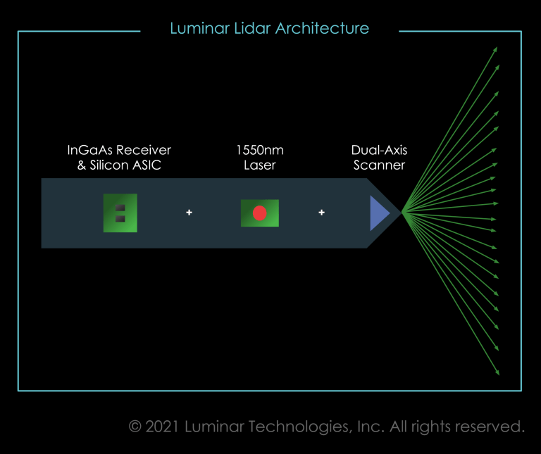
This is why Luminar builds from the chip level up, instead of using off-the-shelf components. Their unique architecture enables them to leap over the common pitfalls that many other lidar architectures face.
Quickly Navigating a Deep Design Space
Three top-level considerations drive the core components: wavelength, ranging method, and field coverage method.
1. Wavelength
The wavelength at which a LiDAR sensor operates determines the semiconductor materials used for the critical optoelectronic components. Further, the control electronics and supply chains associated with these different materials must be aligned – this is one of the reasons why LiDAR companies have a difficult time producing successful products in multiple wavelengths.
Critical to core sensor design and production, wavelength represents a choice between safety and ease. LiDAR technology will be deployed broadly into the public, and these sensors mustn’t increase the risk of retinal damage.
Shorter, near-visible infrared wavelengths (e.g. 905nm) are more hazardous to eyes than longer wavelengths because even though they are not visible, the energy is still focused onto the retina. 905nm is the most common lidar wavelength and is indeed very close to human visibility. This means it is severely limited in how much light it can safely send into the world for measurements.
The path to automotive LiDAR requires measuring objects at long-range, which requires wavelengths that can output significant power while remaining eye-safe. Very early on, Luminar committed to 1550nm LiDAR design – beginning as controversial and then finally becoming the market expectation for long-range LiDAR. This decision has resulted in achieving significantly longer-range detection while remaining a class 1 laser product. An example of this is shown in the graph from the prevailing laser safety standard, IEC60825-1 below (note that “Class 1” is the safest classification).

2. Ranging Method
The ranging method of LiDAR is how the sensor measures each pixel’s distance. One way or another, light energy is encoded and sent out into the world, scatters off-targets, travels back to the sensor, and the device calculates the distance travelled. This light signal can be encoded in time (short pulses) or frequency (continuous wave modulations).
Like any sensor, the quality of each LiDAR range measurement can be improved with an increased signal. For LiDAR, an increased signal can be achieved in three ways: sending more laser light out, collecting more light by increased measurement time, or collecting more light through averaging multiple measurements. LiDAR performance is greatly impacted by signal strength.
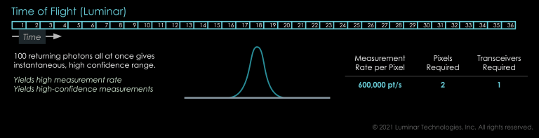
Linear Time of Flight
Luminar uses time of flight (ToF) which sends out a single short pulse for each pixel in the point cloud. This allows for a very fast measurement rate, an immediate understanding of reflectance, and no speed-dependent range error. Other techniques claim benefits over ToF, but have significant trade-offs. At the highest level, they send less light out but have to collect the same amount of signal, meaning they take significantly longer per-measurement.
Single-Photon Detection
Similar to linear ToF, this approach uses short pulses. To force short-wavelength materials into the solution, however, a detector so sensitive it can detect a single photon is used. The tradeoff here is that it does so without knowing how many photons come back, or where they came from. Many pulsed measurements (on the order of 100) must be captured for each pixel to interpret where real targets likely are among all the noise of the sun, headlights, and other sensors.
This technology is well suited in applications like ultra-low-power smartphones and aerial mapping since time is not critical and the scenes under measurement are relatively flat. In the uncontrolled and safety-critical applications of high-speed automotive, neither the susceptibility to interference or the time penalty are acceptable.
FMCW
The same is true, in a different way, for Frequency-Modulated Continuous-Wave (FMCW). This technique effectively spreads the transmitted light energy into a continuous (not pulsed) signal. What can be measured by a pulsed system in nanoseconds takes microseconds to measure – which matters when you need a million or so measurements per second to achieve the perception goals of automotive LiDAR. FMCW is well suited for metrology applications where this trade between measurement quality and time may be taken to the extreme, offering micrometre range accuracy with seconds of integration time. In a vehicle, however, meeting broad performance requirements with this handicap creates an untenable systems proposition.
3. Field Coverage Methods
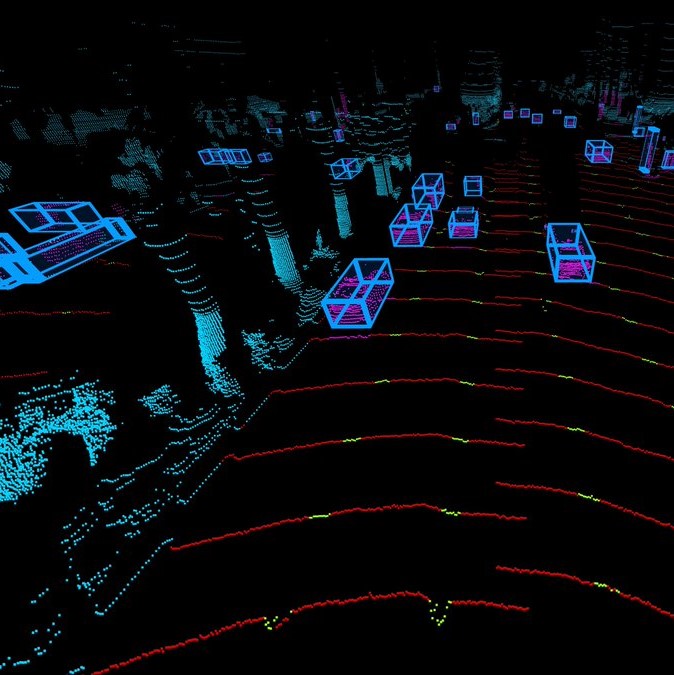
The field coverage method decision encompasses how a sensor distributes and collects light to create a 3D point cloud. The quality of measurement from the field coverage method (e.g., angular pointing accuracy) is as important as the ranging data quality. There are many methods of field coverage, but at a high level, there are; flash, scanned, and hybrid approaches.
Flash
Flash LiDAR functions similarly to a camera, with a detector assigned to each pixel of the point cloud. These architectures commonly operate below 1100nm wavelengths due to the cost of many-detector arrays for longer wavelengths (trading cost for eye safety and thus limiting range). The full scene is simultaneously illuminated, effectively packing the entire frame-worth of laser energy into a single pulse.
In addition to a short detection range, they have a fixed pixels-per-frame and fixed point pattern. This means the sensor must narrow the entire field of view to achieve higher point density in the centre – effectively ignoring much of the roadway. This architecture suffers failure modes in an uncontrolled environment, many the same as cameras:
- Reduced performance in ambient light (e.g. sunlight)
- Geometrical artefacts from bright targets (e.g., traffic signs) due to optical crosstalk
- Geometrical artefacts from obscurants (e.g., snow) due to optical crosstalk
- High levels of LiDAR-LiDAR interference (common scene and direct line of sight)
Mitigation of these failure modes reduces the practical range and resolution even further, rendering flash irrelevant for highway driving – regardless of wavelength or ranging method.
Flash / Scan Hybrid
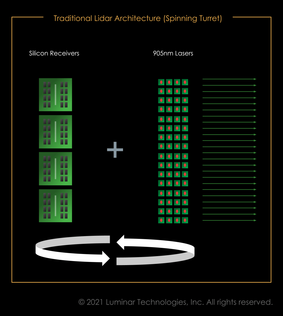
If only one dimension is flash, with the other scanning somehow, it generally suffers the same shortcomings of flash, in one dimension. The most common example of a 1D flash is the rotary turret or “spinner” that pioneered the 3D LiDAR market. 1D scan architectures result in an incremental cost-performance trade-off (e.g., adding a laser and a detector for each additional line) that makes them prone to dilutive product portfolio segmentation and eliminates the provider’s ability to leverage multi-market volume for cost improvements.
This architecture can leverage many off the shelf components, making it attractive to low volume markets since the cost floor can be achieved with minimal investment, and the performance portfolio can meet a diverse need space. In this same architecture family is a pixelated version of flash whereby the transmit laser is “scanned” by sequentially activating an array of lasers. Unfortunately, the high component count required for high resolution keeps the cost floor high for all of these hybrid architectures, and the failure modes of flash render it inapplicable for highway autonomy.
Scanning
Scanning LiDAR means somehow moving the light around the sensor’s field of view. There is a desire to minimise moving parts in LiDAR, based on the idea that moving things are often more prone to failure than static things. Many LiDAR architectures claim to be solid-state with no moving components, but with closer inspection have fragile moving parts.
- MEMS: Small scanning mirrors actuated using Micro-Electro-Mechanical Systems. The core issue here is that the mirrors aren’t actually “micro”, so the scanners are prone to failure, fabrication inconsistencies, and environmental instability. The result is unstable scanners with poor angular fidelity during vibration and shock, which tend to happen in relatively large amounts when driving.
- Silicon Photonics: Optical Phased Arrays and similar approaches integrated into lightwave circuitry fundamentally struggle when coupling light out to the free-space world. While these devices are truly solid-state scanners, they offer very poor efficiency (~75% light lost to the system) and offer poorly organised beams that result in extremely high false-positive detections throughout the scene. Further, tight thermal stabilisation is critical as many of these devices are controlled with local thermal control of the material’s optical properties.
- Liquid Crystal: Technically liquid-state scanners, these devices can be either transmissive or reflective but, like silicon photonics approaches, offer poor efficiency and beam quality. Their scan speed is also dependent on temperature, literally slowing down with lower temperature.
- Scanning Mirrors: While certainly the most “old school” scanning approach discussed here, low-mass motor scanned mirrors are by far the most optically efficient and robust scanning option when considering the gruelling automotive requirements. Luminar leverages a precision 2 axis scanner to meet the performance and cost demands of the industry simultaneously.
By understanding these common architectural pitfalls, Luminar forged a path that didn’t create a performance tradeoff that stood in the way of cost goals to deliver robust safety or useful autonomy. They deliver LiDAR and associated software that meets the industry’s stringent performance and economic requirements to enable safe autonomy.
Browse our range of LiDAR sensors.